HAM: Difference between revisions
(KA6Q ideas) |
(jitsi) |
||
| Line 1: | Line 1: | ||
<big>Amateur Radio "HAM"</big> | <big>Amateur Radio "HAM"</big> | ||
'''<big>Noisebridge Video Conference System "jitsi"<big/>''' | |||
optionally allow your camera and microphone. | |||
'''https://jitsi.noisebridge.io/hackitorium''' | |||
Revision as of 12:06, 15 May 2021
Amateur Radio "HAM"
Noisebridge Video Conference System "jitsi"
optionally allow your camera and microphone.
https://jitsi.noisebridge.io/hackitorium
- https://hackaday.com/2021/05/12/historical-hackers-emergency-antennas-launched-by-kite/
- https://farm8.staticflickr.com/7744/27602747911_3c00f12020_o.jpg
- http://vk2zoi.com/articles/half-wave-flower-pot/
N6NFI
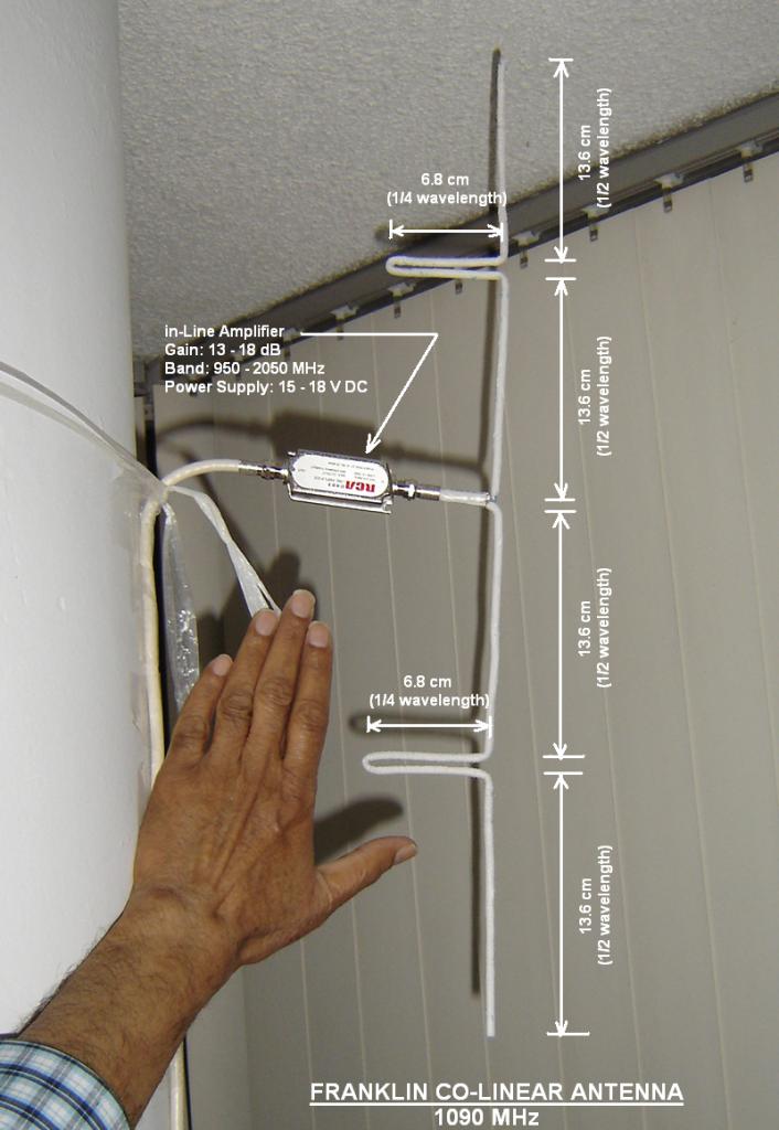
KA6Q Antenna Analysis
Attached some pictures and scribbles.

A sketch of where the Franklin Collinear might fit.
The black line is the sloper, poly rope. Insulating. If you want, can be monofilament nylon (make sure it is UV resistant) to be gossamer invisible.
Red is the vertical antenna. Feed point is somewhere near the bottom ... (doesnt have to be in the center like the textbook Franklin Collinear).
Each section is lambda/2. Each bubble is a lambda/4 stub .. which can be rolled over a cardboard tube (or plastic tube). If you make a hairpin, and carefully coil the twisted bifiliar pair of wires, then the calculation will be easier as the self-inductance of the "coil" will be minimal, but the phasing comes from the stub. If you space out the coil as a single well-spaced layer over a 15cm long tube, then self-capacitance will be minimized. That self-L and self-C are not harmful, but just complicate calculations.
You can also keep the hairpins horizontal and tie each to the orange drop down. Then the calculations are easiest! But it now looks like a ladder .. easier to spot by eye, and counterindicated if you want to keep it stealth.
The Orange drop down is another Franklin Collinear, but it is parasitic. Or it can simply be a straight wire dropdown. Or simply dont make the orange wire; something or the other in the building will be reflective enough. I'd bet the orange is not worth thinking about .. so just 'fuggetaboutit'.
Feed the bottom most end of the red antenna wire with a J-pole like configuration. Needs an extra non-radiating lambda/4 .. but height is cheap, and you need height anwyay -- the bottom parts of the antenna cant see over the terrain.
Tuning a wire antenna will be tight, narrow band. And a Franklin Collinear at N sections, so when you tune the lengths to have tune all of them equally. ie. take apart and rebuild. Painful. So, dont calculate .. get a nanoVNA.
Each batch of wire is different. So forget data sheets for wires, which dont exist anyway. Buy the exact wire you plan to use. From that same batch of wire.
1. Make a dipole - 10% longer than calculation. Hang it as far in 'free space' as you can. Cut an exact tuned dipole for 144.630 using the nanoVNA. (not 144.230 .. tweak your antenna for your Tx not your Rx.)
2. Hang the dipole lambda/4 from the exact yellow wall. Check again with the nanoVNA. (stand far away, operate nanoVNA remotely, is that possible?)
3. Make a two section Franklin Collinear with a J-pole feed. Install lambda/4 from the yellow wall. Check with a nanoVNA.
4. Tweak, discard, make a new one, discard,.... lather, rinse, repeat. Till you have a perfext 2 section collinear for 144.630 MHz.
You will have to adjust the lambda/2 length, the lambda/4 harpin, the lambda/4 j-pole feed. So maybe you will throw away and start with new wire. That's why a 2 segment test case.
The offset of the j-pole feedpoint doesnt matter as long you have perfect resonance (we only care about the dip, no matter what exact resistance value you see at the dip). SWR does not matter. Only dip frequency matters.
5. Now build the 7 or 11 segment Franklin collinear. Check resonance dip with nanoVNA. Should be perfect (else see how much off it is, and make a new antenna everything scaled by that ratio).
6. Finally adjust the feedpoint tap of the J-pole feed for perfect match.
7. If you need to use a coax feed, make the coax be an exact multiple of lambda/2 (after accounting for velocity factor, as measured by nanoVNA, not from speed of light formula). Then coax mismatch will matter least.
 Line to N6NFI (W6YX actually, but that's indistinguishable at
given resolution).
Line to N6NFI (W6YX actually, but that's indistinguishable at
given resolution).
The square grid roads are probably mostly flat plateau. And then "Bernal heights" park clearly slopes down .. as evidenced by the "terraced" roads that follow the terrain.
South of the terraced roads, obstruction buildings are a non-issue.
 After Lowe's Hardware, you are clear over the saltwater amplifier!


The only tall building south of you is Chavez School building. And even that is off the beam, and any case doesnt matter because your beam is probably 36 deg or so wide.

Using this antenna gain calculator as a rough ballpark of beam width angle; to support the above sentence.
...
Oh yea. Indeed. How about a thin tall fiber-glass pole flush against their wall. If the foot of the pole is a meter away from the wall, and on a heavy cinder-block (or drill your root top) that will not budge on your root top, then the pole will bend and push against the wall. Friction will keep it in place. Two monofilament fishing line guy wires forming a triangle, and flat against the wall will make it absoultely still. It is not "attached" to their wall.. (friction is not attachment :-) There's a chap on the street view map who is leaning on that building .. he is not nailed to the wall is he? :-)
You can also put up a freestanding fiberglass fishing pole, and three guy wires. Tigthen the guy wires taut, and the fiber-glass pole will bend a bit and under tension will stay stiff. But I like the pushed against the wall much better.
The theme in the above is something thinner and under tension with friction leveraging the wall might be actualy taller and stronger than a traditional "professional" mast. Insects have stronger muscles, per mass, than the elephant. And gossamer can be stealth.
...
Or maybe he is feeding it by a tap on the center hairpin. So the center hairpin is the quarter-wave matching section. Some of the other people's drawings seems to say that -- which makes sense. If so that'd be okay.
Anyway... that's digging into detail of this specific antenna. Your antenna is different and an opportunity to make entirely other mistakes or get it right in an entirely different way :-)
Talk Net
9am N6NFI Talk Net simulcast:
Microphone and Camera optional, connected to KR6DD echo link audio feed.
https://jitsi.noisebridge.io/HAM
Now Playing:
- All Your RFz - Balint Seeber (DEFCON21)
- - SDR Basics - Balin Seeber (DEFCON26)
- IM Hacks Garage - Samy Kamkar (OWASP 2016)
Next hack!?
https://hamprojects.info/brian-SM/
A-N-D

[EXMPERIMENTAL]
LIVE Stream: rtmp://space.noisebridge.info/live/HAMbridge
Open in VLC as network stream (Ctrl + N)
This is a test stream directly from our FPGA based streaming box. It is up most of the time and running a test feed with an HDMI input and overlays with VGA from pegasus showing tmux with performance and weather information. The stream may not start properly, and I sometimes have to try loading it a few times for the video to stream properly. There is audio from Mary piped in but it usually quite. Looking to switch this over to monitor SDR or the like as well.
Want to talk radio or the like, open jitsi meeting available, there may or may not be anybody home: https://jitsi.noisebridge.io/HAM
The main noisebridge hangout is here, and is more likely to have something going on:
https://jitsi.noisebridge.io/hackitorium
Band Plan: http://www.arrl.org/graphical-frequency-allocations
Space
- Frequencies & Info on contacting the International Space Station
- Current position and track of ISS
- Satellite & Space Contacts
Suggested HT (handheld transevier) TH-D72A
Paired with AL-800 (clone) Antenna
HF
HF stands for High Frequency. In today's RF landscape this is the low end of the frequency band generally from around 3-30Mhz or 160-10 meter wavelength.
Propagation Reports & Forecast International Beacon Project
ATV
ATV is Amateur Television broadcast and receiving.
Information on setting up an ATV station
APRS
DEF CON HAM Radio Village APRS Demo
Hardware:
Packet Radio
https://portal.ampr.org/index.php
Resources
Hardware
- Noise Bridge R-15
- QRP CW Transceiver
- RTL-SDR.com
- SDRplay
- Speach/Accessibility friendly HT Radiooddity GD-77
Clubs
Links/News
Antennas
2m (VHF)
- https://everydayready.wordpress.com/2015/10/19/diy-2m-tape-measure-yagi-antenna/
- https://offgridsurvival.com/2meterantenna-homebrewdroopygroundplane/
- http://iz8jji.blogspot.com/2011/04/roll-up-2m-jpole-antenna.html
40m (HF)
Vertical Antenna
https://www.electronics-notes.com/articles/antennas-propagation/vertical-antennas/vertical-types.php
G5RV Dipole
https://en.wikipedia.org/wiki/G5RV_antenna
Works ideally suspended horizontally above the ground. Inverted V is also common with greater then 90 degree spread.
Bay Area Repeaters
VHF 2m (144-148 Mhz)
2m/70cm Repeater Book Entries within 25mi of Noisebridge
Testing uplink and downlink analog capabilities starting on the 2 meter band, the following stations have been confirmed working from the East Bay with relatively low power setups.
Callsign     Frequency   Offset       Tone      Location        County
--------------------------------------------------------------------------------
K6EAG        145.130     -0.6 MHz     127.3     Hayward         Alameda
W6RGG        147.240     +0.6 MHz     107.2     San Leandro     Alameda
W6PW         145.150     -0.6 Mhz     664N*     Sutro Tower     San Francisco
WB6NDJ       146.880     -0.6 Mhz     77.0      Oakland         Alameda
WA6TOW       146.925     -0.6 Mhz     114.8     North Peak      San Mateo
N6NFI        145.230     -0.6 Mhz     100.0     Palo Alto       Santa Clara
WR6ABD       146.640     -0.6 Mhz     162.2     Loma Prieta     Santa Clara
KI6AOZ       146.085     +0.6 Mhz     114.8     Newark          Alameda
W6CX         147.060     +0.6 Mhz     100.0     Mt. Diablo      Alameda

Tone: Unless otherwise noted is up-link tone frequency in Hz
      * Uses DCS on Rx/Tx
UHF 70cm (420-450 Mhz)
WW6BAY 443.975 100.0
Tone Control
DTMF
Try '699' on N6NFI
DCS
- http://mmi-comm.tripod.com/dcs.html
- https://wiki.radioreference.com/index.php/DCS
- http://www.repeater-builder.com/tech-info/ctcss/ctcss-overview.html
SDR
Satellites
https://publiclab.org/notes/sashae/06-26-2020/diy-satellite-ground-station