DreamTeam/Brainduinov2
June 2018. Masahiro brings the latest Brainduino EEG from his recent work at Neurofox in Berlin. We'll be meeting Masahiro at Noisebridge on Friday June 8th and at CircuitLaunch on Saturday June 9th and possibly also Sunday June 10th.
This Brainduino is built from several modules soldered onto a main board using a Teemsy 3.2 to pull 24-bit samples via SPI from an Analog Devices AD7173 ADC. This data is transmitted via serial port to a separate Bluetooth chip which can provide a reliable data stream at rates such as 250 samples per second for 2 channels. The system is can be powered via 5 volt USB external battery pack, or optionally with an integrated internal battery.
Seperate modules provide signal amplification and filtering via op amps (Analog Devices OP4177, Burr-Brown OPA2111) and a low-pass filter (Maxim MAX7480), along with necessary voltage converters etc.
OP4177 and OPA2111 op amps on the "blue" modules above are arranged to provide 2 pairs of differential amplifiers boosting the approximately 100 microvolt EEG signal by a factor of 1000. Maximum input up to +/- 2.5 millivolts is amplified to produce output of +/- 2.5 volts. D-Amp converts +/- 2.5 volts to 0-5 volt range.
The "red" module has 4 of the MAX7480 8th-order lowpass Butterworth switched-capacitor filters. The cutoff frequency for these filters can be set via software. There are 4 low-pass filters because we have balanced output from the the amplifier board. There is a 555 timer producing a clock signal which can be used to provide a default clock for the MAX7480 lowpass filters cutoff at 32 Hz. With a direct connection bypassing the filter there is a 200 Hz limit due to main amplifier specification - depends on ADC sampling speed. (Errors with too much high frequency going to ADC, resulting in sampling error.)
(The Teensy interrupt timers on this brainduino are usually used instead of the 555).
The module also has the D-Amp for transforming the +/- 2.5 volts to 0-5 volts to connect to ADC.
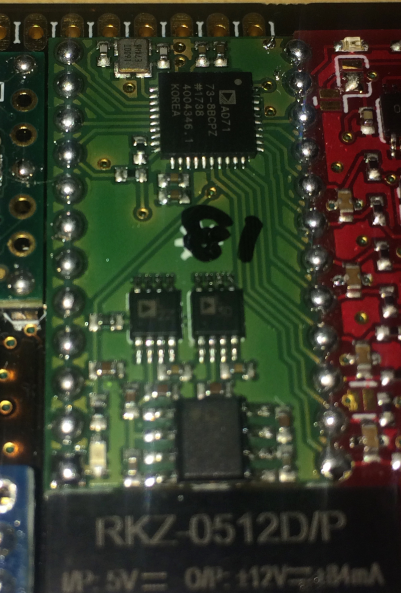
The "green" module supports the AD7173 ADC. The ADC is always receiving 0-5 volts on all analog input pins by design. Software allows setup of bipolar mode, meaning that difference between 2 selected pins is calculated. This allows output of potentially 0-10 volts. Pin1 is 0 volts, pin2 is 5 volts, then pin2 - pin1 is 5 volts. In case pin1 is 5 volts and pin2 is 0 volts, then difference is calculated as -5 volts. (...)
Typical range +/- 100 microvolt for EEG signal is amplified by a factor of 1000, resulting in output range of +/- 0.1 volts for the signal of interest (out of the total 10 volt range, which may be driven by larger noise from muscles.) This would seem to indicate roughly 18 bits of our signal reflect the EEG.


